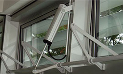
Understanding the linear actuator working principle is essential for engineers, equipment manufacturers, and purchasing teams who need reliable motion solutions.
In the modern landscape of industrial automation, robotics, and smart home technology, the ability to achieve controlled, straight-line motion is essential. Whether you are adjusting a medical bed, positioning solar panels, or automating a manufacturing line, the BESTOP linear actuator serves as the backbone of reliable performance.
But how exactly does this device transform simple electrical energy into precise physical force? This article breaks down the mechanics and applications of BESTOP linear actuators.
What is a Linear Actuator?
A linear actuator is a mechanical device designed to convert rotational motion—typically generated by an electric motor—into linear (straight-line) motion.
While a motor spins in circles, a BESTOP linear actuator translates that torque into a push-and-pull movement. This makes it an ideal solution for tasks requiring lifting, lowering, sliding, or tilting. Unlike hydraulic systems (which use pressurized fluids) or pneumatic systems (which use compressed air), BESTOP electric linear actuators offer a clean, maintenance-free, and highly precise alternative.

Linear Actuator Working Principle
Linear actuators transform energy—whether electrical, hydraulic, or pneumatic—into controlled, bidirectional motion along a single axis. While standard motors provide continuous rotation, linear actuators deliver precise, straight-line force. Given their ubiquity in modern automation, the mechanical conversion process of electric linear actuators serves as the industry-standard model for this operational principle.
The core philosophy of a BESTOP linear actuator lies in its elegant energy conversion chain. Here is how it functions step-by-step:
- Electrical Input: Power is supplied to the actuator’s integrated DC motor.
- Rotational Generation: The motor’s rotor spins, generating rotational torque.
- Torque Transmission: Through a series of internal gears (a gearbox), this high-speed, low-torque rotation is converted into a lower-speed, higher-torque output.
- Motion Conversion (The Lead Screw): The gearbox rotates a threaded lead screw (or spindle).
- Linear Translation: A drive nut is threaded onto the lead screw. Because the nut is constrained from rotating, it is forced to move axially along the screw as the screw turns.
- Extension/Retraction: This movement of the nut pushes or pulls the extension tube (the piston), creating the desired linear output.
What are the Main Components of a Linear Actuator?
Understanding the main linear actuator components helps engineers and purchasing teams evaluate actuator design and select the right solution for their applications.
The main components of a linear actuator include:
- Electric Motor: Provides the driving force by converting electrical energy into rotational motion. The motor type directly affects actuator speed, torque, and power efficiency.
- Gearbox: Reduces motor speed while increasing torque output, allowing the actuator to handle higher loads and operate smoothly.
- Lead Screw: Converts the motor’s rotational movement into linear movement through the screw and nut mechanism. The screw design influences actuator efficiency, precision, noise level, and service life.
- Nut Assembly: Moves along the screw and transfers rotational motion into the extension and retraction of the actuator rod.
- Actuator Tube and Housing: Protects internal components from dust, moisture, and mechanical damage while providing structural support for the actuator.
- Limit Switches: Control the actuator’s end positions by stopping movement when the maximum or minimum stroke is reached, helping prevent mechanical overload.
- Controller and Feedback System: Manages actuator operation by controlling direction, speed, position, and synchronization with other equipment.
Technical Specifications for Linear Actuators
The performance of a linear actuator is determined by several key specifications, which affect its force, movement range, speed, durability, and application suitability. Understanding these parameters helps engineers and purchasing teams select the right actuator for their specific requirements.
| Specification | Description |
|---|---|
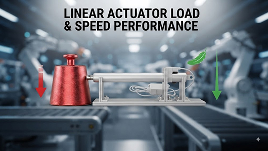
| Load Capacity | Determines the maximum force an actuator can generate when pushing or pulling a load. Proper load selection ensures stable operation and prevents premature wear. |
| Stroke Length | Defines the maximum distance the actuator can extend and retract. The required stroke depends on the movement range of the application. |
| Speed | Indicates how quickly the actuator moves during operation. Different applications may require high-speed movement or slower, more precise positioning. |
| Voltage | Specifies the electrical power required for operation, with common options including 12V DC and 24V DC based on system requirements. |
| Duty Cycle | Defines how frequently and how long the actuator can operate within a given period. Higher duty cycles are important for demanding industrial applications. |
| Position Accuracy | Determines how precisely the actuator can reach a target position, which is critical for automation and positioning systems. |
| IP Rating | Indicates the actuator’s protection level against dust and water, helping determine whether it is suitable for indoor, outdoor, or harsh environments. |
| Operating Temperature | Defines the temperature range where the actuator can maintain reliable performance under different working conditions. |
| Control Method | Refers to how the actuator is operated, including options such as manual switches, remote controls, PLC systems, and feedback control. |
Linear Actuator Applications
Linear actuators are widely used in various industries where controlled linear movement, precise positioning, and automated adjustment are required. With advantages such as compact design, easy control, low maintenance, and reliable performance, electric linear actuators have become an important motion solution for industrial equipment, commercial systems, and smart devices.
Common linear actuator applications include:
- Industrial Automation: Used for machine adjustment, automated production lines, material handling systems, robotic equipment, and other applications requiring precise and repeatable movement.
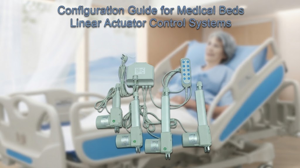
- Medical Equipment: Applied in electric hospital beds, patient lifts, medical chairs, and positioning systems to provide smooth and reliable adjustment functions.
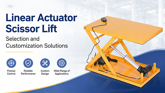
- Smart Furniture: Commonly used in adjustable desks, electric recliners, lifting tables, and other furniture systems that require quiet and convenient movement control.
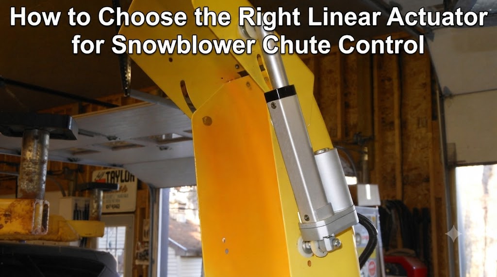
- Agricultural Machinery: Used for automatic adjustment of equipment components, such as positioning systems, ventilation controls, and agricultural automation solutions.
- Robotics and Automation Systems: Provide accurate linear motion for robotic arms, inspection equipment, and automated mechanisms.
- Construction and Heavy Equipment: Applied in lifting systems, access platforms, and machinery requiring powerful linear force and reliable operation.
- Automotive Applications: Used in vehicle adjustment systems, electric tailgates, seats, and other automotive mechanisms requiring controlled movement.

Electric Hospital Bed

Home Care Bed

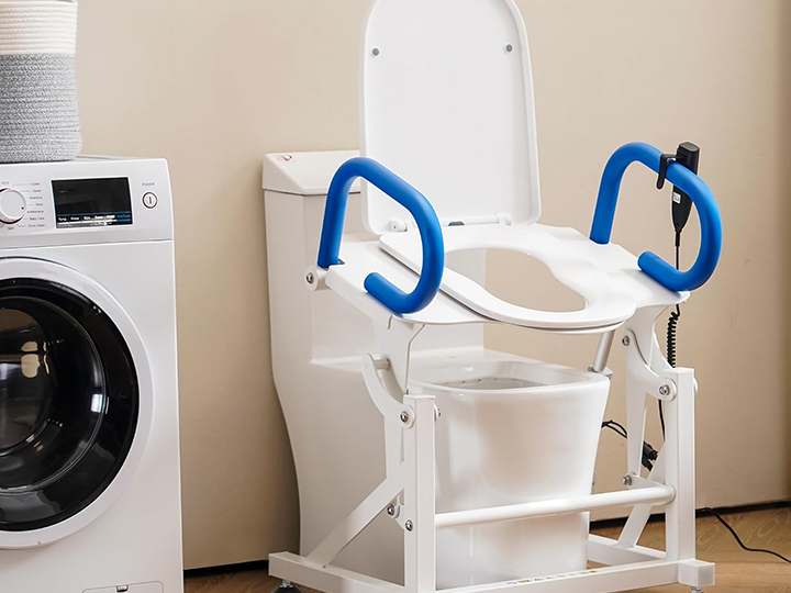
Toilet Lift
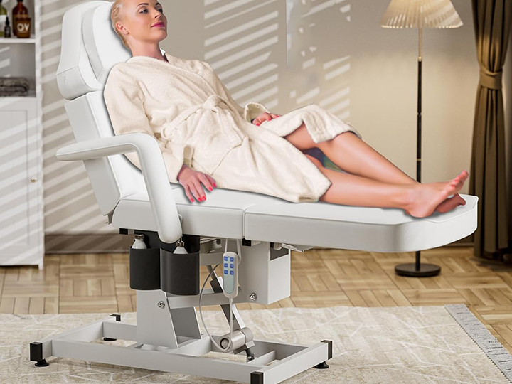
Treatment Chair

Operation Table

Stand up Desk

Wheelchairs
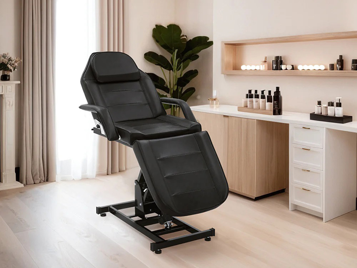
Massage Table
What are the Common Malfunctions of Linear Actuators?
Although linear actuators are designed for reliable and long-term operation, improper selection, incorrect installation, overload conditions, or harsh operating environments may cause performance issues over time. Understanding common linear actuator malfunctions helps engineers and users identify problems quickly, reduce downtime, and improve the service life of the actuator.
- Actuator does not move – caused by power supply issues, wiring problems, or motor failure.
- Slow or weak movement – usually related to overload, insufficient power, or internal wear.
- Abnormal noise – may result from worn gears, screw damage, or insufficient lubrication.
- Actuator stops unexpectedly – possibly caused by limit switch issues or control system errors.
- Overheating – often caused by excessive load, high duty cycle, or unsuitable operating conditions.
- Uneven movement – may occur due to installation problems, misalignment, or mechanical resistance.
Proper linear actuator selection, correct installation, and regular maintenance can help prevent these common issues and extend the service life of a linear actuator.
How to Choose the Right Linear Actuator?
Selecting the right linear actuator requires a clear understanding of the application requirements, operating environment, and performance expectations. The correct actuator should match the required force, movement range, speed, control method, and working conditions to ensure reliable operation and long service life.
When choosing a suitable linear actuator, consider the following key factors:
- Define the motion: lift, slide, tilt, push, pull, or position.
- Calculate force with load, friction, pivot geometry, and safety factor.
- Choose stroke length from the required travel, not just the gap size.
- Decide speed under load.
- Choose voltage and size the power supply for current draw.
- Check duty cycle against the expected run-rest pattern.
- Match the IP rating to dust, rain, washdown, or outdoor exposure.
- Decide whether feedback or synchronization is required.
- Check mounting geometry and side-load risk.